
Designing Solar Systems in 3D Mode (DSM)
3D Mode uses DSM terrain data to generate a realistic site model and allows PV modules to be placed directly on roof surfaces. This mode is ideal for creating and adjusting module layouts in complex rooftop environments.
Enter Drawing Mode
Before placing modules, select the desired PV module model and module color from the left-side panel.
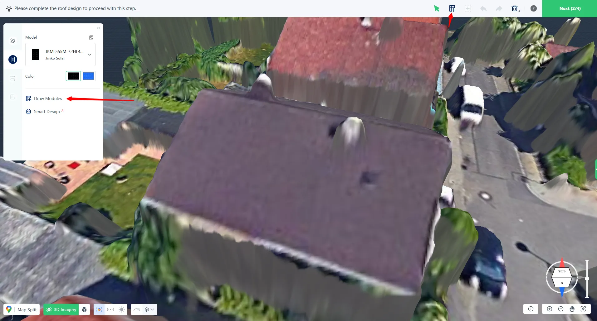
You can enter drawing mode in either of the following ways:
- Click Draw Module from the left-side panel
- Click the Draw icon from the top toolbar
Once activated, the cursor will switch to module placement mode.
Create Module Arrays
Click on the roof surface to place the first module. The system automatically detects the roof slope and aligns modules with the roof surface.
To create multiple modules, click and drag across the roof area. Modules will be generated continuously until the mouse button is released.
Single modules can also be placed individually using separate clicks.
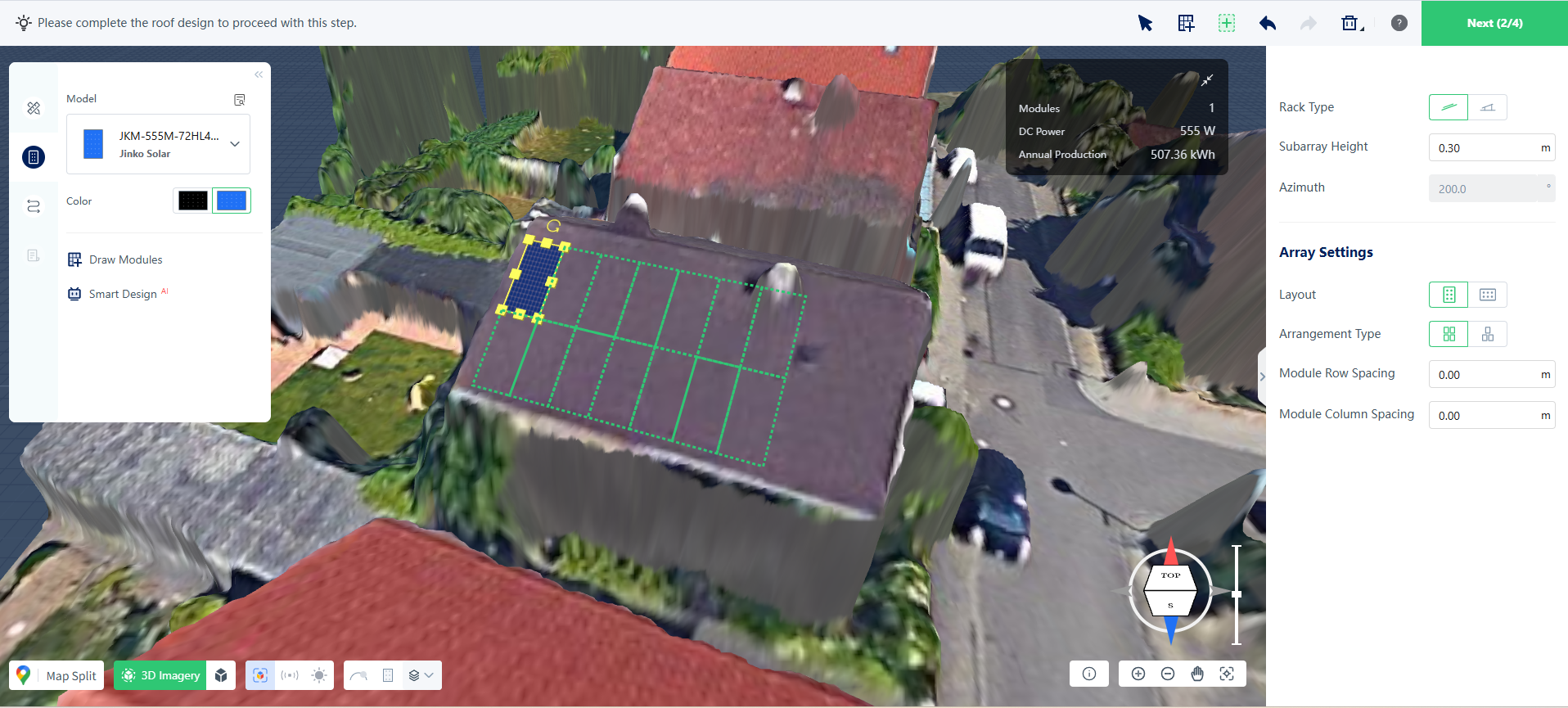
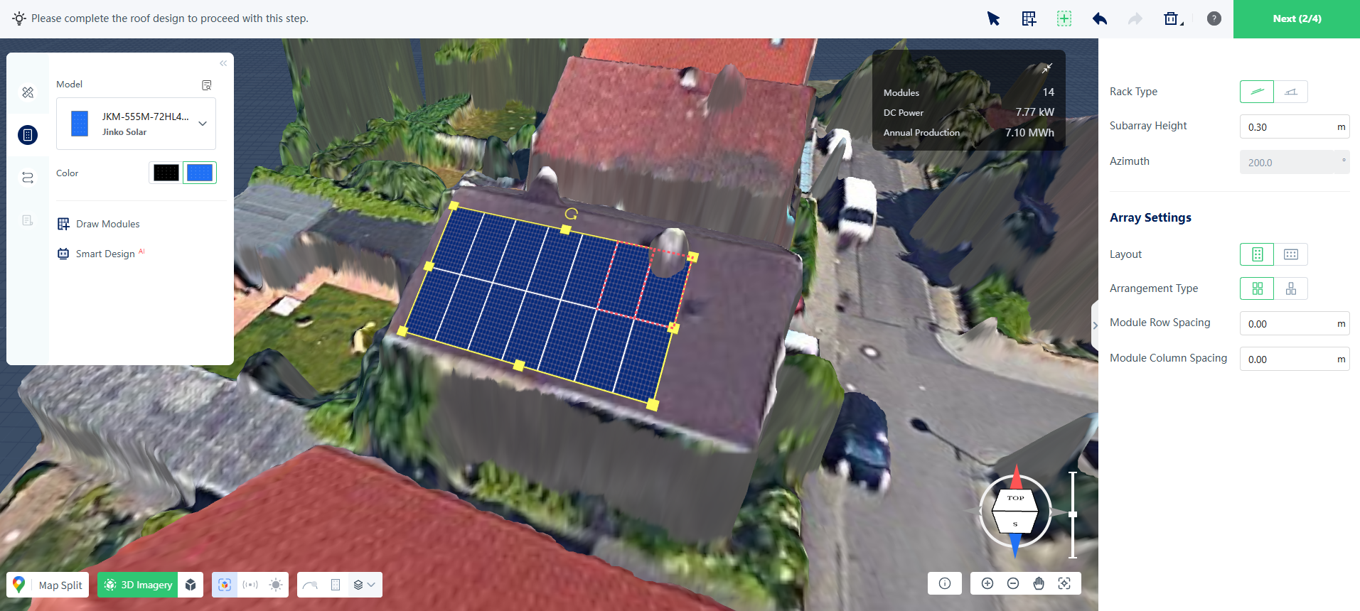
When editing an existing array, move the cursor outside the array boundary to modify its coverage:
- Green frame indicates the area where modules will be added
- Red frame indicates the area where modules will be removed
Right-click at any time to cancel the current drawing action.
Edit a Selected Array
After an array is selected, several adjustment options are available.
Resize the Array
Drag the control points around the array boundary to adjust its overall size.
Change the Layout Direction
Use the rotate handle to modify the orientation of the module array.
Adjust Layout Parameters
Layout settings can be edited from the right-side properties panel, with changes applied in real time.
Add or Remove Modules
Additional module editing tools are available from the top toolbar when an array is selected.
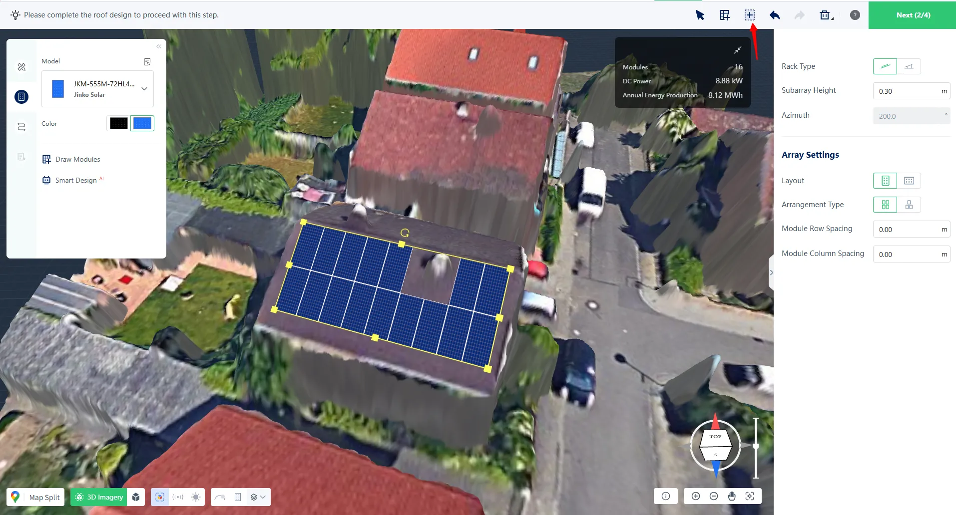
You can:
- Add or remove individual modules
- Add modules within a selected area
- Remove modules within a selected area
Green selection frames indicate module addition, while red selection frames indicate module removal.
Complete Your Layout
Once the layout is finished, review the module arrangement and continue with the next design steps, such as electrical design, shading analysis, or report generation.